Structures: Interlocking Triangulated Facets.
The objective of this project is to introduce a basic understanding of structure and construction principles through research, design and production of a full size 3D structure.
During Part I (Research)
I surveyed a few buildings:
1. Japanese Pavilion In Hanover - Shigeru ban Architects
2. Expo 2000 Pavilion - Thomas Herzog
3. Endesa Pavilion - IaaC
Whilst initially being asked to study different types of timber construction, the ease at which Timber can be used to create sustainable architecture was very appealing. The various different types of Timber that exist as well the various different thicknesses it can be obtained in was very also appealing. One of the architectural works that infuenced our thought process and ultimately our structure was the ‘Endesa Pavilion’ in Barcelona. Although extravagant from the outside because of its use of cantilevers and jagged, spike like edges, the interlocking structure of the building was particularly fascinating. Interlocking is basically the combination of objects that cross into one another to form a new shape. In this particular case, deliberate gaps were left in the pieces of timber placed horizontally in the base, in which the pieces of timber placed vertically would slot into. The simple nature of this construction method was what was most appealing for our group, particularly considering how a building of decent magnitude could essentially be built, and allowed to stand, from a pure, interlocking process. The image directly to the right is a model made to show exactly how the structure works, particularly focusing on the framework and how that’s used to make it stand.
Prior to combining a triangular layout with this interlocking structure method, an initial, individual idea was made to convey this. Inspired by a bird cage like look, a complete interlocking structure was creating from base to its roof and ‘cage’. Considering this construction method, creating a structure that focused on the idea of enclosure and limited space was key, making it feel almost prison like, locked away even. Below are images to showcase what was designed, and how it worked.
Part II: Design Development
Here are a few ideas that were sketched within the group produced via our research. From the sketches, you begin to witness the development of the initial idea with the foundation of multiple triangles.
Here are sketches from the beginning of this idea drawn. From these sketches you can see a development of how the idea was very different in the first place and how we developed and changed things. Starting with how the structure began by looking like an upside down boat with cantiliver steps extruding outwards. To a triangluar facet design inspired by the cellular style structure, with cantiliver steps extruding inwardly. This gave us a further improved idea in terms of function and design to incorporated the triangular facets throughout the design in the form of a base and curving over canopy.

We decided to have our design based on cellular construction. Cellular construction is a method of building bridges and other structures that was invented in the early 20th century (building American suspension bridges). The method involves constructing towers from relatively small welded steel box units. The small welded steel box units are called box girders.


Part III: Final Design & Production Information
Initially being asked to study and research different types of timber construction we also reasearched the properties such as density, fire resistance and durability, we realised the ease at which timber can be used to create sustainable architecture was very appealing.
**One of the architectural works that influenced our thought process and ultimately our structure was the ‘Endesa Pavilion’ in Barcelona. Although extravagant from the outside because of its use of cantilevers and jagged, spike like edges, the interlocking structure of the building was particularly fascinating. Interlocking is basically the combination of objects that cross into one another to form a new shape. In this particular case, deliberate gaps were left in the pieces of timber placed horizontally in the base, in which the pieces of timber placed vertically would slot into. The simple nature of this construction method was what was most appealing for our group, particularly considering how a building of decent magnitude could essentially be built, and allowed to stand, from a pure, interlocking process. The image directly to the right is a model made to show exactly how the structure works, particularly focusing on the framework and how that’s used to make it stand.


Interlocking chair - searching, we came across this chair as an idea for our canopy. She thought this was an example or idea how we could fix the joints together on our structure.
What is Timber Framing?
Timber framing is a method of timber construction that relies on the timber frame as the primary structural support for the building. Timber Framing is a centuries old construction method of creating timber framed structures jointed together with wooden pegged mortises and tenon joints. People have been living in timber framed structures for thousands of years. The reasons for this is, the ready supply of wood for timber frames, the ease of construction, the durability of the material and its aesthetic appeal.
Benefits of Timber Framing
Fast, efficient and cost effective
The comparative studies of the economics of different wall framing systems indicate that, in terms of direct building expenses, timber frames are consistently the most cost-effective solution.
Durable
Timber buildings correctly designed and maintained can have an inde␣nite life. Timber structures last for a life time.
Flexible to add further extensions
The timber frame method of building gives designers ␣exibility in both layout and external appearance. High levels of thermal insulation are incorporated within the construction, reducing heating costs and conserving energy
Environmentally friendly
Timber is the most environmentally responsible building material. Timber has low production energy requirements and is a net carbon absorber. Timber is a renewable resource.
Strong and lightweight
Timber is strong, light and reliable making timber construction simpler and safer than steel or concrete construction. Timber has strength for weight ratio 20 per cent higher than structural steel and four to ␣ve times better than unreinforced concrete in compression. Wood is strong in tension, compression and bending, allowing triangulated space-frames of trusses and cantilevered structures. There are a wide variety of types of timber frame truss that can be used. The majority of these can be divided into "closed" or "open" trusses.
There are numerous types of wood that you can use for timber frames. The most common ones used are oak, Douglas Fir, larch, pine or modern day Glue lam. Oak: Oak is one of the main timbers used for timber framing. It has been a building material for more than because of it strength, durability, beauty and easiness to work
Douglas-Fir, Larch, Pine: Douglas-Fir is an impressive pine tree. The wood has very good structural qualities and has a particularly high weight/strength ratio. It is easy to cut providing the cutting tools are sharp otherwise it as a tendency to splinter on the cutting edges. Larch, is valued for its tough, waterproof and durable qualities. It is also easy to process, but is highly resinous. Pine, easy to process and cheap.
Glue lam: Modern timber frame structures can also be made from glue laminated wood which gives a timber frame a more contemporary style. Gluelam or laminated beams are specially sorted woods, where the bad bits are cut out, then finger jointed and glued together in any dimension you want. The quality and strength is superior to normal wood so you can used it in bigger spans, thinner dimensions etc. So it can save money. It is also available in oak. In some structural construction it can replace steel and concrete and be a cheaper alternative.
http://www.timberstructures.net/timber-framing.html

Here above is a clamp with nuts and bolts that I developed to maintain stability towards the base working in the same way as the roof trusses does I initially thought this procedure would work well to securely hold the structure of the base alongside the wall of the canopy of the design.
In the last set of screenshots of the initial design idea, the junctions are conjoined together as another alternative structured triangle. Above you can see the indication marks establishing how the functions of this systematic junction operates. We suggested that this design could be securely affixed down onto the base with the front part of the components going vertically down to be situated right at the point.


Above here are another set of screenshots showing separate components which affix together as a triangle by interlocking. Additionally we tried to figure out how this particular type of junction would fit with the mid part of the base replacing the original triangles.


Exploded Render

Composite Render - Showing The Junction
We discussed how our design was going to work mathematically.
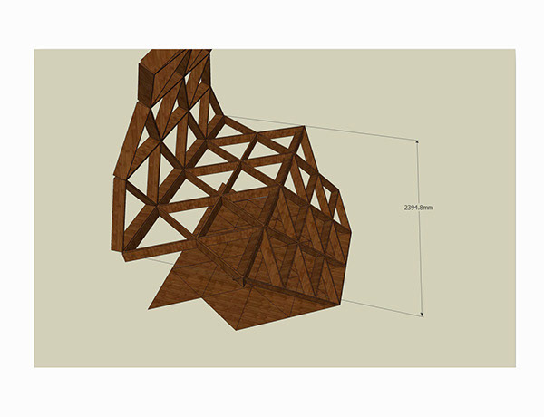
Before we went ahead with the design, we had to decide how wide we wanted it to be. If we used triangles of 600mm, then it would be 2400mm as there are four triangles. If we made the width 1500mm, we could make smaller triangles (300mm) and five of these. Below is the current design which we have to make smaller.
From this we all agreed (300mm) rows of five triangles would work best as it is something at least one person can stand on.
We worked on the structure in two halves. The bottom and top; the bottom would support the top (the canopy). In order to work out how the the canopy would hold we had to design a strong and dependent base that would work solely on it’s own to hold the canopy, finishing the structure.

We next needed to decide on the depth of the structure; with the width being at 15cm we decided 96cm was a good depth to work with. We understood less was better as that would make the structure more stable due to the reduced torque.

Connection plates could be used on both sides to connect the straight strips, bolts would secure the three layers together.
Cantilever
A Cantilever is a beam which provides stability at only one end. The beam then acts as a carrier and it carries all the load to the support where it is all forced by the "moment". the moment is an effect produced by a force acting at distance of an object, in this case the structure. When using a cantilever constriction it allows you to design extrude, extend or hang something over.
Cantilevers are normally only supported by the body of the building. Cantilevers are divided divided into two parts, the first part is the part which is elongated; the second is the half bottom that reduces the stress, this means the structure becomes much stiff. If the cantilever cannot handle all of the stress, the cantilever itself could make an arc going downwards or even break and resulting in collapsing.
Cantilevers can have a massive effect on how a space is viewed and used. Cantilevers make it possible for more space without increasing the footprint. There are many uses for cantilevers, their appearance, the shadows, the thought process and the structure.
Torque
The amount of cantilever is a crucial to the strength of the structure. Our aim for this design was to extend the platform as much as possible without substantially weakening it’s structure, so to reach a balance between aesthetics and stability. We reduced the platform by 200mm and also added more material to the corners, as a result we reduced the overall torque at the base corner form above 200Nm to just a little over 100Nm.


Now we needed to work out how many sheets we'd need in order to make our structure. This is the layout for the base which only needed four sheets.
So far we were happy with the design, but we were not convinced that the base would take the load of a person. So we came up with solutions, the first one was to add support to the back, and the other was to add more material to the corners, and at the same time also have single larges pieces . We decided to proceed with the second option as it stays true to our goal to produce a structure that gives the illusion of levitation.

Abandoning the connectors meant that the pieces would be stronger as it now would be one piece, it also reduced the mass and cost of the structure extra connector pieces and bolts would no longer be need. Fewer parts for the base meant that it would be easier for us to build.

The advantages with this layout is that fewer pieces are cutout, and although the layout seems wasteful, it is in-fact the most economical way to build our structure as connectors are no longer needed. With this layout, we would require a total of seven 2440mm x 1220mm x 18mm sheets of ply.

This is our first model testing out the layout, from this model we realised that we need to add stabilisers to stop the legs from spreading. We designed to have the intersection at 60 degrees for the top and bottom and 120 degrees for the sides, this meant that the slots had to be enlarged to allow for the steeper angle, these larger slots also meant that the angles can be reversed – (the base would be lowered)


We needed to work out how we would put the structure together. We drew up some sketches on cable ties which hold together the canopy of the structure.To hold the canopy together the idea of using cable ties and drilling holes within the triangles, and i also thought about using rope. It would provide texture as well as extra strength.

We decided that using cable ties was the best way to connect the triangles, this would allow flexibility in how we place each triangle as all the triangles would have 5 holes on each side to attach the cable ties.

This animation shows how the individual triangles would behave without any connections, this helps us understand what the cable ties will be supporting. We realized that the canopy has no interdepending stability at all, so we stated looking into geodesic domes.
Geodesic Domes
Definition: A geodesic dome is a sphere-like structure composed of a complex network of triangles. The triangles create a self-bracing framework that gives structural strength while using a minimum of material. The term geodesic is from Latin, meaning earth dividing. A geodesic line is the shortest distance between any two points on a sphere.

Construction/ how they are connected...
- Wooden Domes -
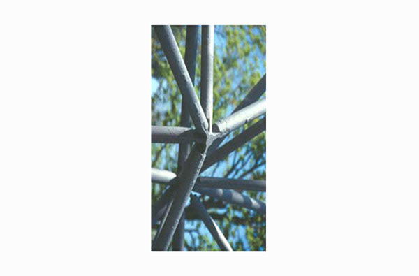
(This type of dome is often called a hub-and- strut dome because of the use of steel hubs to tie the struts together.)
Have a hole drilled in the width of a strut, which is a rod, or bar forming part of a framework and designed to resist compression.
This method allows the struts may be cut to the exact length needed. Triangles of exterior plywood are then nailed to the struts.
The dome is wrapped from the bottom to the top with several stapled layers of tar paper, in order to shed water, and finished with shingles. This allows weather proofing too.
- Panellised Domes -
Constructed of separately framed timbers covered in plywood.
The three members comprising the triangular frame are often cut at compound angles in order to provide for a flat fitting of the various triangles.
Holes are drilled through the members at precise locations and steel bolts then connect the triangles to form the dome. These members allow more insulation to fit with the triangles.
The panelized technique allows the one to easily attach the plywood skin to the triangles while safely working on the ground. This method does not require expensive steel hubs.

Buckminster Fuller's Geodesic Domes

Biosphere US Pavilion
Encloses some 2,200,000 cubic feet of space inside a globe that is 165 feet in diameter. The outer surface is composed of 954 triangular panels made of a polyethylene core sandwiched between two anodized aluminum plates. These panels are not all the same size and they used three- dimensional units, a triangle on the outside, hexagonal on the inside, and curved to fit a given arc, as its structural basis. By connecting them together in the shape of a dome, it distributed the structure's weight over the whole surface.
Geodesic Domes Cont...
Advantages
The triangle is a very stable shape; for example, a force applied to the corner of a rectangle can deform it to come a parallelogram, but the same force will not deform the triangle. This makes geodesic dome buildings highly resistant to such forces such as snow covering and wind. The triangle withstands the pressure and is much more rigid
- It is twice as strong as a rectangle.
- A geodesic dome supports itself without needing internal columns or interior load – bearing walls. - Geodesic domes are east to build.
Disadvantages
Cutting triangles from sheet materials is wasteful.
- It is hard to seal, and lights can be detected throughout the entire structure due to the lack of privacy

Experimenting with canopy form
The influence of The Sydney Opera House and the use of Post-Tensioning.
Initial Problems
As a group, considering the initial work creating inter-locking and triangular structures, incorporating the two into one design was vital. So sticking to the idea of a curved, geodesic dome like canopy, proved testing in trying to incorporate a structural theory that would allow it to work.
Although the triangular designs and shapes would be connected via cable ties, creating a canopy that would hold each shape at exactly the right angle to create an overall curve was the most important part of the structural design, without that it wouldn't’t work.
Post-tensioning, an architectural precedent established by engineers in the 1950’s when working on the Sydney Opera House, seemed the most reliable and functional idea to use.

The Use of Post-Tensioning
It was designed and built throughout the mid 20th century, but its ambitious style of architecture meant that it wouldn’t have stood up unless the designers/engineers ‘overcame some formidable engineering challenges’. Jorn Utzon’s proposal, was at firrst dismissed (Richard Hammond proclaims in a documentary on the National Geographic television network) because engineer Ove Arup, feared he couldn’t build Utzon’s winning design. “The problem was lots of big, curved shapes, and Utzon didn’t want columns to hold them up either. Arup knew that the magic of the design would be compromised with traditional concrete construction; they could never achieve the delicate shapes Utzon wanted. Arup’s answer was to make a frame for each sail, out of huge hollow concrete ribs. But it had never been done before at the scale required.”The biggest ribs were 55 meters high, they were too big and heavy to mold in one piece, very similar to the structural issues of weight and curvature within out design. The solution to their design, and ours is demonstrated in a collapsible toy. “Toys like these are made of individual segments, held together with the cord. When this cord is removed it collapses. Arup decided to make the huge ribs out of segments, which would be pulled together to make the right shape, just like this collapsible toy.
The technique is called post-tensioning, which strengthens the structure whilst also keeping it together in unison. It threads all the pieces together. “Post-tensioning cables are like puppet strings that hold an arch up. Once the cables are threaded, they need to be tightened or post-tensioned per se, so they then become the things that hold the arch up.” Simply put, it's just a series of sections held together by the tension running through it. However, in our design, the thread wouldn’t be put thought it because the pieces aren’t as thick as those used in Jorn Utzon’s design. Wire would be placed along the back of the canopy, and the length of the wire would in essence determine the curve of the canopy. Utzon’s design was held together using huge steel cables and stopped from spreading by epoxy glue. In our design, the wire is tied onto cable rope clamps, with the use of turnbuckles to tension the cables. The second image on the left showcases this.
The technique is called post-tensioning, which strengthens the structure whilst also keeping it together in unison. It threads all the pieces together. “Post-tensioning cables are like puppet strings that hold an arch up. Once the cables are threaded, they need to be tightened or post-tensioned per se, so they then become the things that hold the arch up.” Simply put, it's just a series of sections held together by the tension running through it. However, in our design, the thread wouldn’t be put thought it because the pieces aren’t as thick as those used in Jorn Utzon’s design. Wire would be placed along the back of the canopy, and the length of the wire would in essence determine the curve of the canopy. Utzon’s design was held together using huge steel cables and stopped from spreading by epoxy glue. In our design, the wire is tied onto cable rope clamps, with the use of turnbuckles to tension the cables. The second image on the left showcases this.


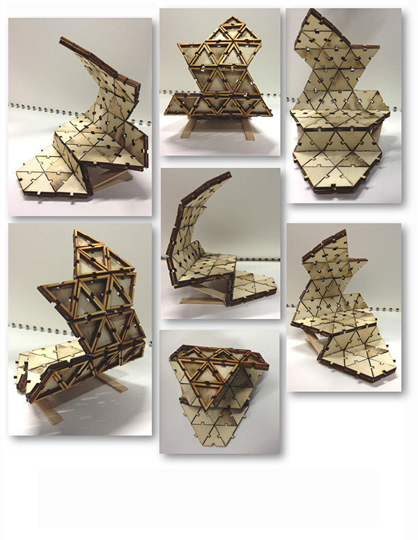
Design Model I
The design came together really well, upon the assembly of this model it was brought to our attention that there was still plenty to consider before our final design model such as functionality and assembly. We had to calculate to make sure that the weight would be distributed equally. As the model shows, its being bonded by glue and vaguely paints a picture of how the actual structure will be held together.

This is the final design idea, following the first model and after a re-assesment the changes that were made was that we decided to keep the triangular facets together.
With the bottom of the design now having two layers worked better using a puzzle system. The top layer of the model which consists of four triangle is solely for cosmetic reasons rather than functionality.
After the first model we realised that there was two potential points where the structure could snap and the canopy could collapse, so we began experimenting with braces along the front and back of the structure. Even up until this point we still hadn't figured out a secure way for the structure to stand alone and were using a cradle at the back for support.
From the second model we realised that the weight would pose a problem and would be another factor we would now need to consider. The top of the structure needed to be lighter than the bottom to balance it out. With the puzzle system in position and keeping everything together with the designs dual layers, we made the canopy's second layer hollow to balance the weight out therefore producing less of a chance of the canopy collapsing.

Part IV: Fabrication, Tests & Assembly


The base will be assembled with the front facing the floor, this would make it easier to hold as the mass of the pieces are supported by the ground. We will first place the front pieces on the floor (white), then we will slot in the rear pieces (light grey). Stabilisers (dark grey) will then be slid in before rolling it to its correct orientation, - the cut in the front will ensure that orientating the base is easier.
As the canopy has 9 sections, we can divide the task of fastening the cable ties between 3 member (3 per member) then join the larger sections.


Fin.


